Reprap 3D Printer Build Log: 2nd Entry
Here’s update 2. I was hoping to be a little further along for this update, but if building a 3dprinter teaches you anything, it’s that anything can go wrong and you need to be willing to adapt and have patience. Also, a set of small files, a soldering iron and a drill will be your best friends in this journey. I really suggest you spend $5-10 on a set of these:

I left off last time with having tested the ramps board, the stepper drivers/motors and the PSU. Next up is building out the Y-axis that the bed moves along on, then the upright frame that holds rods for the X and Z-axis. When I first started trying to put the extruded aluminum into the printed parts, I was surprised with how tight the fit was. This, it turns out, is normal, I just had to use my files and drill when necessary to get things to fit. Oh yeah, and make sure you put all your t-slot nuts in BEFORE you seal off the ends, it’s hard to pull these things apart once they are put together. And one more thing, when assembling the frame and X,Y,Z axis, it’s very important that everything is square. If it’s not, it’s going to be hard to get your printer to print straight lines.
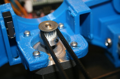
I mentioned earlier that not everything goes according to plan, the first instance of this was when I tried to attach the Y-axis motor. The plastic was thicker than expected and the screws were too short. So I went to the next length up of my M3 screws, but these were too long for the threads on the motors which is why I have those extra nuts on the screws in the pic below.
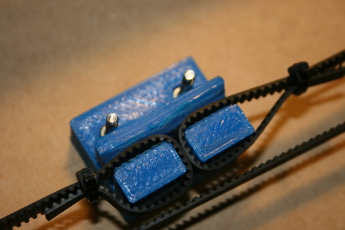
After attaching the motor, and drilling the MDF board and attaching it to the bearings, which went smoothly, came the next hangup, the Y-belt holder. This is a tricky part in assembling the Y-axis. First, I had some trouble getting the belt to fit into the grooved slot in the belt holder, but after lots of filing, and some use of the heat gun (which I don’t really think is the greatest idea, but sometimes you gotta get crazy) I got it to fit. After that, getting the belt attached and keeping it tight is hard to do with just one person, so if you have a friend around willing to lend a hand it really helps.
Ok, so now I have the Y-axis assembled, I’ve made sure it’s square, and the bed slides along the smooth rods easily. YAY! Next is assembling the upright frame, which is what will hold the X and Z axis and the electronics mount to it as well. And the Y-axis too. It’s pretty straightforward, but like before, make sure everything is square. This directly impacts your ability to print accurately. And triple check that you are inserting the t-slot nuts in the correct positions. I goofed on this and I will need to improvise now on how to hook up the lcd display. I’m not going to get into much detail on the frame, it’s fairly simple.
Here’s the frame and Y-axis together, but not yet attached (the upright frame is actually backwards in this pic).

Next came the X-axis. This one seemed fairly easy as well, but I hit a pretty big snag on this one, and I learned that it is a common issue in the community. For some reason (that I’m not entirely sure I understand fully, I’m learning as I go, so feel free to correct me if I’m wrong) when the STL file gets sliced up by whatever slicer you are using, the inner diameters shrink up by as much as 0.5mm. You can read about it here, and see what the community has to say on GitHub. This can make fitting parts together very difficult, even with lots of sanding and filing. The part that gave me the most trouble was the X-end motor and idler. I had been filing the insides of the holes for the linear bearings for quite some time, and was able to get them to fit in the X-end idler.

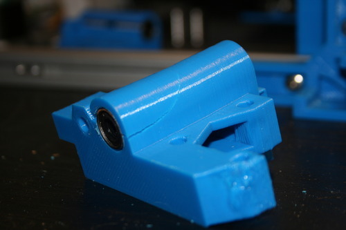
But, things went badly for the X-end motor mount. You can see in the pic below that it cracked.
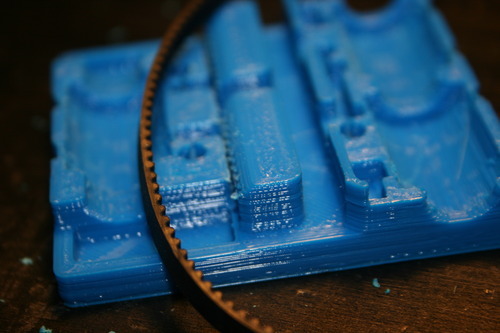
After that happened, I thought maybe it wouldn’t matter and I would just move on and finish assembling the X-axis and that would be one of the first parts I would print and replace. But when I was testing to see if the belt would fit into the X-carriage I discovered that it too suffered from the shrinking effect, and it would be nearly impossible to get that belt to fit. You can see to the right of the belt is where it is supposed to go, and it’s nearly closed off.
After discovering this I contacted Marty, who is the designer of this variation on the RepRap theme, and is also the person who sold me the printed parts. He is an awesome, and very helpful dude. I asked for replacement parts and he was more than happy to get me new ones and he even explained to me what had happened and why, pointing me to the issue open on github. Very, very helpful guy and obviously passionate about 3dprinting. He has a Youtube page here that documents the assembly of the Wilson TS and he has an eBay store where you can get various parts. And from what I hear, he is really good about answering your questions.
So, while I’m waiting for new parts I’ll be assembling the extruder, and doing anything else I can. Stay tuned!
2 Notes/ Hide
sqyttles-blog reblogged this from randallzaitz
randallzaitz posted this